“Hari plaast” DIRECT ACTION HAND PUMP
 Research and developments have given birth to a new pump i.e. ”Direct Action Hand Pump” and is covered under IS:14106:1996. It is designed to draw water from bore wells with static water level up to 15 meters. Without any lever action, pumping efforts is applied directly on handle for which it is named as “Direct Action” hand pump. They are cost effective than the deep well hand pumps for medium lifts and are safer bacteriological contamination and corrosion problems.
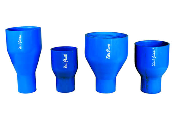
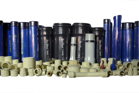
The Major Components of the pump are:
- Head and Handle assembly.
- Pedestal assembly.
- Riser pipe 3M long (Top one is separate from other pipes)
- Hollow Pvc connecting (Pump) rods, 3M long (makes the pumping action easy due to buoyancy effect)
- Top pump rod 1 M long (special attachment for connecting with handle)
- Pistion Rod 1 M long (pistion assembly is attached to this rod)
- Cylinder pipe along with foot valve arrangement.
- Upper casing (80 mm dia), lower casing (40mm dia), Reducer, Screen pipe, Sand trap assembly etc.
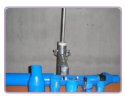
INSTALLATION
DIMENSIONS OF DIFFERENT COMPONENTS FOR DIRECT ACTION HAND PUMP
| Item | Nominal
dia |
Outside dia | Wall Thickness |
Length |
||
|---|---|---|---|---|---|---|
| Min | Max | Min | Max | |||
| Upper Casing | 80 | 80 | 88.3 | 4.0 | 4.6 | 3000 + 10 |
| Rising Main | 50 | 60 | 60.2 | 2.5 | 3.0 | 3000 + 10 |
| Lower Casing | 40 | 48 | 48.2 | 3.5 | 4.0 | 3000 + 10 |
| Top Pump Road | 32 | 42 | 42.2 | 2.2 | 2.7 | 1000 + 10 |
| Pump Road | 32 | 42 | 42.2 | 2.2 | 2.7 | 3000 + 10 |
| Sand Trap | 40 | 48 | 48.2 | 3.5 | 4.0 | 1040 + 10 |
| Piston Rod | 32 | 42 | 42.2 | 2.2 | 2.7 | 1000 + 10 |
| Cylinder Pipe | 50 | 60 | 60.2 | 2.5 | 3.0 | 3000 + 10 |
LIST OF COMPONENTS FOR ONE SET DIRECT ACTION HAND PUMPS
| S.NO | ITEM DETAILS | No required for well depth
|
||
|---|---|---|---|---|
| 15 Mtr | 30 Mtr | 40 Mtr | ||
| 1 | Pump Head Assembly | 1 | 1 | 1 |
| 2 | Handle Assembly | 1 | 1 | 1 |
| 3 | Stand Assembly | 1 | 1 | 1 |
| 4 | Pump Rod | 2 | 3 | 5 |
| 5 | Pump Rod Top | 1 | 1 | 1 |
| 6 | Piston Rod & Piston Assembly | 1 | 1 | 1 |
| 7 | Cylinder & Foot Valve Assely. | 1 | 1 | 1 |
| 8 | Rising Main | 1 | 2 | 4 |
| 9 | Rising Main Top | 1 | 1 | 1 |
| 10 | Upper Casing | 3 | 4 | 6 |
| 11 | Lower casing | 1 | 5 | 6 |
| 12 | Robo Screen. | 2 | 2 | 2 |
| 13 | Screen coupler | 1 | 1 | 1 |
| 14 | PVC Reducer | 1 | 1 | 1 |
| 15 | Sand trap | 1 | 1 | 1 |
| 16 | C.I.Cutter Plug. | 1 | 1 | 1 |
| 17 | Retrieving Rod | 1 | 1 | 1 |
| 18 | Combination Spanner | 1 | 1 | 1 |
| 19 | Solvent cement | 100 gms | 150 gms | 200 gms |
CURATIVE MAINTENANCE PROCEDURE FOR DIRECT ACTION HAND PUMP
Curative maintenance is carried out when a malfunction needs correction through replacement or repair of some of the components of the hand pump. The first step is curative maintenance is to identify the reasons for the malfunctioning of the hand pump.
| Investigation | Observation | Corrective Action | |
|---|---|---|---|
| 1 | Check discharge of pump | Discharge is about one Ltr. Per stroke.
Discharge is less than approx. one Ltr per stroke |
Pump does not need repair
There is a problem in the below ground assembly Pump piston, foot valve assembly needs repair. |
| 2 | Check efforts needed for pumping | Excessive pumping effort is needed before pump yields water. | Check static water level in the tube-well. Hand-pump operates best in areas where water level is within a depth of 45 to 48 M. If water goes below this depth, operation of the hand pump will be difficult due to lesser buoyancy. |
| 3 | Check working of the handle | Handle rises gently and smoothly. Play of the handle in the guide bush is more than 5 mmHandle does not rise on its ownHandle rises very rapidly and with a jerk. | The pump is function normally.
Top guide bush needs replacement. There it is excessive friction between the handle and the Top Guide Bush . The pump piston needs to be checked. Indicates a piston related problem. The cup washer may have worn off and may need change. |
| 4 | Check handle surface of the portion where it moves in the Top Guide Bush | The portion shows were and tear and signs of corrosion | Handle needs to be replaced. The old handle should be sent for galvanizing.. |
| 5 | Check if there is any dry stroke. |
Water comes out from the first to the fifth stroke.
More than five dry strokes before water comes out. |
The Hand-pump is functioning normally.
There is leakage in the below ground assembly, Foot valve, Cylinder and Riser pipe joints need to be checked. |